
This is a continuation of my previous blog post on the introduction to quantum logic gates.
In this blog, we are focusing on doing some exercises using qiskit to implement some classical circuits. If you have some understanding of basic quantum gates like CNOT and Toffoli, you can jump right in 🙂 . Else, please go through the previous blog to learn the basics about gates.
Before starting, we should understand that there is no practical advantage of re-implementing classical circuits using quantum gates. Quantum circuits will give a lesser performance while consuming much more power. We are doing this exercise just to get more familiarized with quantum gates by implementing something we already know 🙂 .
Now you must be worrying about why we should learn about a computer that has lower performance and higher power consumption. Unfortunately, the performance gain from a quantum computer can be realized only by learning quantum algorithms like Deutsch-Josza Algorithm. ( which we will do in a future post ).
Prerequisites
If not already have, please install qiskit on your machine using this guide or Youtube video.
Addition
Classical computers use 0s and 1s for their data representation. And the most basic operation a computer can do on those data is adding two of them together.
The following example shows the addition of two binary numbers.
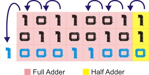
In classical computers, this addition is implemented using half adder and full adder circuits.
A half adder takes two inputs and produces one output and a carry-out bit. We can use half adder to add the least significant bits in the above example. This is the only position we can use a half adder since in all the other places we need to consider the carry-in bit.
A full adder takes three inputs ( two bits + one carry-in bit) and produces one output and a carry-out bit.
The following diagram shows the half adder and full adder circuits in their logic forms.

Half-Adder using quantum gates
Looking at the classical logic of the half adder, we need XOR and AND gates to be implemented using quantum gates. For this purpose, we can use fundamental quantum gates like CNOT, X, and CCNOT (Toffoli) gates as buildings blocks. We don’t need gates like Hadamard gate since we need only the fundamental quantum states. ( |0> and |1> )
Step 01
So as the first step, let’s create an XOR gate using basic quantum gates.
…… done 🙂 , we don’t have to combine several gates, CNOT gate is the answer.
Let’s recap what the CNOT gate does. It simply changes (flip) the value on the second bit depending on the value of the control bit. If control bit = 1 flip else no change.
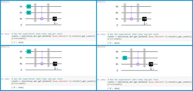
The following diagram shows the execution of the CNOT gate under all input combinations. Inputs, gates, and output measurements are separated from barriers. In the gate sign, line with the dot (q0) is the control bit. Line with the (+) sign (q1) is the bit that is being changed.
In Qiskit qubits are initialized to |0>. When we need to create |1> we must use a not gate which is shown with a blue box with X in the diagram.
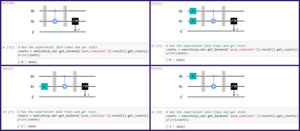
Let’s try to understand the execution of the last scenario. Their q0 is initialized to 1 and q1 is 0. Since the control bit is 1 CNOT gate is flipping the bit in q1. Then when we measure the q1 we get the result as 1.
Following is the code I used to generate the above examples. Try it yourselves for all the input combinations. You can comment, uncomment lines 9 and 10 to change the inputs.
This file contains bidirectional Unicode text that may be interpreted or compiled differently than what appears below. To review, open the file in an editor that reveals hidden Unicode characters.
Learn more about bidirectional Unicode characters
| from qiskit import * | |
| from qiskit.tools.visualization import plot_bloch_multivector | |
| from qiskit.tools.visualization import plot_histogram | |
| # Creating a circuit with 2 quantum bits and one classical bit | |
| qc = QuantumCircuit(2,1) | |
| # Preparing inputs | |
| qc.x(0) # Comment this line to make Qbit0 = |0> | |
| qc.x(1) # Comment this line to make Qbit1 = |0> | |
| qc.barrier() | |
| # Applying the CNOT gate | |
| qc.cx(0,1) | |
| qc.barrier() | |
| # Measuring Qbit1 and put result to classical bit | |
| qc.measure(1,0) | |
| # Drawing the circuit diagram | |
| qc.draw(output='mpl') | |
| # Run the experimient 1024 times and get stats | |
| counts = execute(qc,Aer.get_backend('qasm_simulator')).result().get_counts() | |
| plot_histogram(counts) |
Step 02
We need one more gate to create the half adder, which is AND gate.
For that, we can use the CCNOT gate, which is also called the Toffoli gate.
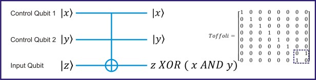
We can see that there is an AND operation between the two control Qubits. If we can use control qubits (x and y) as input qubits we can achieve the AND operation. Then the result of AND is XOR with input qubit (z). If we can make Z always equal to 0 it will not flip the results of the AND operation. In another word, we are using the Z qubit as an ancillary bit.
 Following is the code for AND gate.
This file contains bidirectional Unicode text that may be interpreted or compiled differently than what appears below. To review, open the file in an editor that reveals hidden Unicode characters.
Learn more about bidirectional Unicode characters
| from qiskit import * | |
| from qiskit.tools.visualization import plot_bloch_multivector | |
| from qiskit.tools.visualization import plot_histogram | |
| # Creating a circuit with 3 quantum bits and one classical bit | |
| qc = QuantumCircuit(3,1) | |
| # Preparing inputs | |
| qc.x(0) # Comment this line to make Qbit0 = |0> | |
| qc.x(1) # Comment this line to make Qbit1 = |0> | |
| # no changes to Qbit2 (stays |0> always) | |
| qc.barrier() | |
| # Applying the CCNOT gate | |
| qc.ccx(0,1,2) | |
| qc.barrier() | |
| # Measuring Qbit2 and put result to classical bit | |
| qc.measure(2,0) | |
| qc.draw(output='mpl') | |
| # Run the experimient 1024 times and get stats | |
| counts = execute(qc,Aer.get_backend('qasm_simulator')).result().get_counts() | |
| plot_histogram(counts) |
Step 03
Now we have all the ingredients, its time to go ahead and create the half-adder circuit.
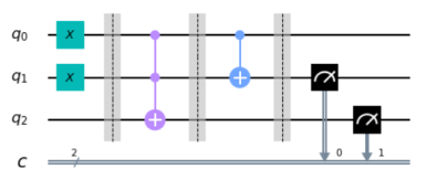
The above circuit diagram shows the full implementation of half-adder. Note that we cannot interchange the two gates because after the XOR gate q1 is changed from the original input.
Code for the half adder.
This file contains bidirectional Unicode text that may be interpreted or compiled differently than what appears below. To review, open the file in an editor that reveals hidden Unicode characters.
Learn more about bidirectional Unicode characters
| from qiskit import * | |
| from qiskit.tools.visualization import plot_bloch_multivector | |
| from qiskit.tools.visualization import plot_histogram | |
| # Creating a circuit with 3 quantum bits and 2 classical bits | |
| qc = QuantumCircuit(3,2) | |
| # Preparing inputs | |
| qc.x(0) # Comment this line to make Qbit0 = |0> | |
| qc.x(1) # Comment this line to make Qbit1 = |0> | |
| # no changes to Qbit2 (stays |0> always) | |
| qc.barrier() | |
| # Applying AND operation and put result to Qbit2 | |
| qc.ccx(0,1,2) | |
| qc.barrier() | |
| # Applying XOR operation and put result to Qbit1 | |
| qc.cx(0,1) | |
| qc.barrier() | |
| # Reading outputs | |
| qc.measure(1,0) # Reading XOR value ( sum bit ) | |
| qc.measure(2,1) # Reading AND value ( carry-out bit ) | |
| qc.draw(output='mpl') | |
| # Run the experimient 1024 times and get stats | |
| counts = execute(qc,Aer.get_backend('qasm_simulator')).result().get_counts() | |
| print(counts) |
Full-Adder using quantum gates
Step 01
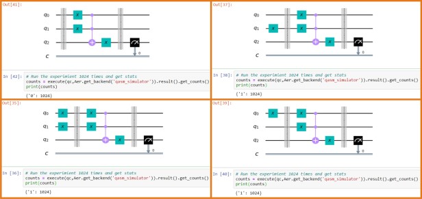
Other than the building blocks we already have, we need a classical OR gate to be implemented using quantum gates.

The above image shows how we create the OR gate using only NAND gates. With the quantum NOT and AND gates in our toolbox, let’s try to create a quantum OR gate.
Code for the OR gate
This file contains bidirectional Unicode text that may be interpreted or compiled differently than what appears below. To review, open the file in an editor that reveals hidden Unicode characters.
Learn more about bidirectional Unicode characters
| from qiskit import * | |
| from qiskit.tools.visualization import plot_bloch_multivector | |
| from qiskit.tools.visualization import plot_histogram | |
| # Creating a circuit with 3 quantum bits and one classical bit | |
| qc = QuantumCircuit(3,1) | |
| # Preparing inputs | |
| qc.x(0) # Comment this line to make Qbit0 = |0> | |
| qc.x(1) # Comment this line to make Qbit1 = |0> | |
| # no changes to Qbit2 (stays |0> always) | |
| qc.barrier() | |
| # OR gate implementation | |
| # Adding NOT opration to inputs of AND gate | |
| qc.x(0) | |
| qc.x(1) | |
| # AND gate | |
| qc.ccx(0,1,2) | |
| # Adding NOT operation to output of AND gate | |
| qc.x(2) | |
| qc.barrier() | |
| # Measuring Qbit2 and put result to classical bit | |
| qc.measure(2,0) | |
| qc.draw(output='mpl') | |
| # Run the experimient 1024 times and get stats | |
| counts = execute(qc,Aer.get_backend('qasm_simulator')).result().get_counts() | |
| print(counts) |
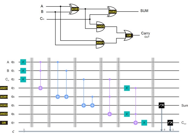
Step 02
We came a long way and now we have all the ingredients need to create a full adder. We just have to combine 2 XOR, 2 AND and 1 OR gate.
Please try to implement this yourself without looking at the implementation first 🙂 then you can compare if needed.
Code
This file contains bidirectional Unicode text that may be interpreted or compiled differently than what appears below. To review, open the file in an editor that reveals hidden Unicode characters.
Learn more about bidirectional Unicode characters
| from qiskit import * | |
| from qiskit.tools.visualization import plot_bloch_multivector | |
| from qiskit.tools.visualization import plot_histogram | |
| # Creating a circuit with 8 quantum bits and 2 classical bits | |
| qc = QuantumCircuit(8,2) | |
| # Preparing inputs | |
| qc.x(0) # Comment this line to make Qbit0 = |0> | |
| qc.x(1) # Comment this line to make Qbit1 = |0> | |
| qc.x(2) # Comment this line to make Qbit2 = |0> ( carry-in bit ) | |
| qc.barrier() | |
| # AND gate1 implementation | |
| qc.ccx(0,1,3) | |
| qc.barrier() | |
| # OR gate1 implementation | |
| qc.cx(0,4) | |
| qc.cx(1,4) | |
| qc.barrier() | |
| # OR gate2 implementation | |
| qc.cx(2,5) | |
| qc.cx(4,5) | |
| qc.barrier() | |
| # AND gate2 implementation | |
| qc.ccx(2,4,6) | |
| qc.barrier() | |
| # OR gate implementation | |
| qc.x(3) | |
| qc.x(6) | |
| qc.ccx(3,6,7) | |
| qc.x(7) | |
| qc.barrier() | |
| # Measuring and put result to classical bit | |
| qc.measure(5,0) # ( sum ) | |
| qc.measure(7,1) # ( carry-out ) | |
| qc.draw(output='mpl') | |
| # Run the experimient 1024 times and get stats | |
| counts = execute(qc,Aer.get_backend('qasm_simulator')).result().get_counts() | |
| print(counts) |
Thank you for making up to here, hope you enjoyed 🙂

I spend more time on abstraction of material science, however, getting into gate levels when we talk about computing gives me larger spectrum! Thanks for sharing!
LikeLiked by 1 person
Glad you liked it 🙂
LikeLike
heloo
when i am executing the program i am getting error like this
Traceback (most recent call last):
File “”, line 19, in
counts = execute(qc,Aer.get_backend(‘qasm_simulator’)).result().get_counts()
NameError: name ‘execute’ is not defined please help me out
LikeLike
Very helpful. Thank you. Is there anything about subtraction?
LikeLike